Copyright © 2018 Li Hui plastic mold Co.,Ltd.
NEWS
Company News
Industry Trends
FAQ
Effect of tool bending on part deflection in injection molding
Hereby is presented an analysis on possible solutions to be applied in order to reduce the mismatch introduced by general accepted approximation of real tool behavior, two different approach have been investigated.
Tool Bending Calculation
The first approach proposed consider modelling the whole tool and run a simulation considering the tool itself as an insert allowing the simulation software to calculate itself the tool bending and the relative effect on the injected polymer.

It must be clear since the beginning that within this approach, which is surely more time demanding in terms of computing and pre-processing, the result strongly relies on boundary conditions set for core-shift calculation and on settings of computation parameters, which influence the stability of calculation.
In the presented case the boundary conditions as set as follow:
- Fixed condition at interface with back plate
- Cylindrical condition on columns
- One side moving condition on parting plane
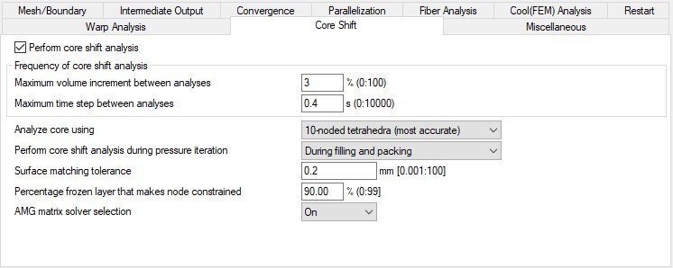
The Core Shift calculation settings are set considering higher frequency of updates respect to proposed standard. Calculation is performed during filling and packing considering 10 nodes tetrahedra mode.
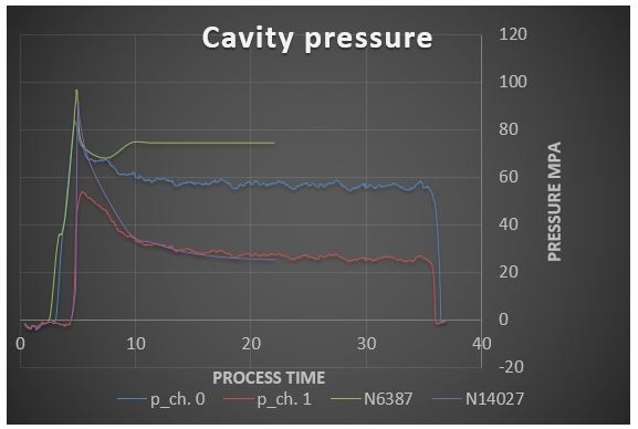
The result of calculation is reported on the picture below. it is clearly visible that tool deflects more on the outside areas increasing significantly the part thickness, whereas it is very stable in the middle.
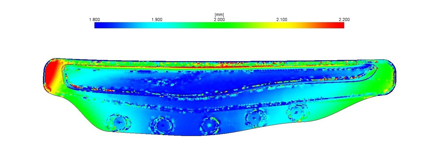
This scenario is completely opposite to the experimental observation, in fact in the real case the sensor A, which is positioned in the middle of the tool, reports the maximum deflection and so the maximum thickness increase.
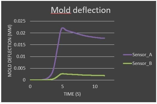
The experiment highlights that tool deflection is really difficult to manage due to complexity of interaction between all the tool components.
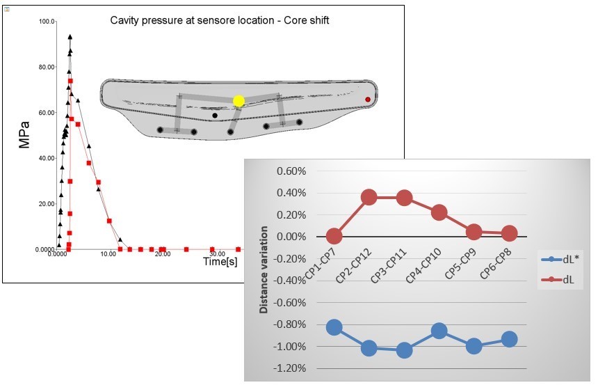
Beside that, the results highlight also another important aspect: that there’s not any impact of tool deflection neither on pressure behaviour nor on deflection. This is because in the Autodesk Moldflow® 2017.3 module of core shift calculation the interaction between insert and plastic component is limited to the freezing time of polymer, after that time no more interaction is calculated.
Tool Compliance Method
The second approach investigated in order to improve the cavity pressure evaluation consist in a coupled flow analysis and tool deflection by activating a back door option in Autodesk Moldflow® 2017.3 proposed and developed by Dr. Franco Costa.
The method consist in adding a variable thickness ∆t at each time step of simulation according to the following: ∆t = Cm * Fclamp
Were Fclamp represent the clamping force at given time and Cm is the Mold Compliance, which is measured in mm/tons and represents a characteristic of each tool.
The basic idea of the approach is to calculate an average global tool opening according to clamping force value at each time instant by a constant factor depending of tool stiffness.
In this specific case Cm value has been calculated by considering the average deflection value measured by force sensor.
This method has been proved to work and provides an easy way to consider the spring back effect of tool during the packing phase, contributing significantly in reducing the mismatch between simulated and real cavity pressure.
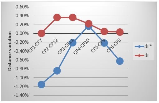
As consequence also the overall deflection prediction results significantly improved reaching a very good matching in some points. Some variation are still present but it maybe possible that depends on other factor than tool deflection and need to be investigated separately.